The decision to build a Goat glider came to us based on its simple design and amateur-friendly construction techniques. However later it turned out that it is far more complex, having tremendous amount of parts which took a lot of man-hours despite their simplicity…
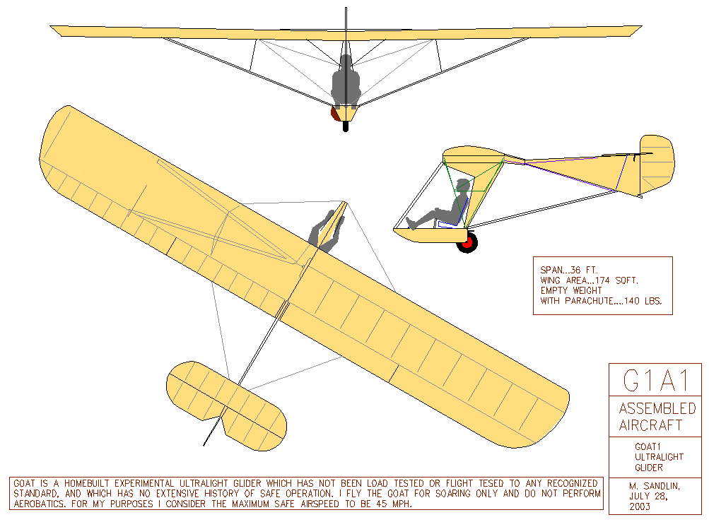
Goat is an open-source ultralight sailplane project designed and developed by Mike Sandlin, who shares the sailplane’s technical drawings to the public.
So far multiple Goats and its derivatives have been built by amateurs as well as commercial products, including motorized AVIAD Zigolo MG12.
After going through original Goat drawings we decided to make some of the technical solutions slightly different. For example, all the ribs for wing, tail and control surfaces would be made of glass fiber composite sandwich panels and carbon fiber sheets. Having access to CNC machining and sheet laser/water cutting, some elements would differ from original ones. Flight controls would be actuated by steel cables (elevator and rudder) and by torque tubes (ailerons). Also we’d slightly change the shapes of wingtips and tail trailing edges.
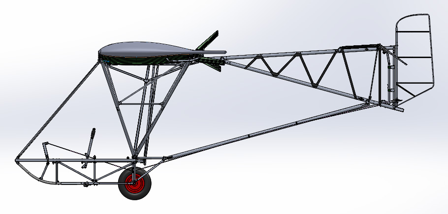
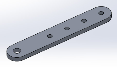
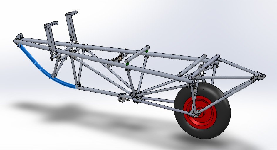
To accommodate all these modifications and facilitate production process we decided to create a highly detailed CAD model of our derivative of the Goat sailplane.

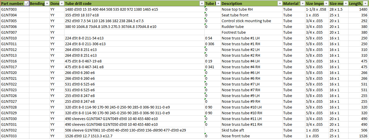
During CAD development every part received its unique part number and a parts catalog was created.
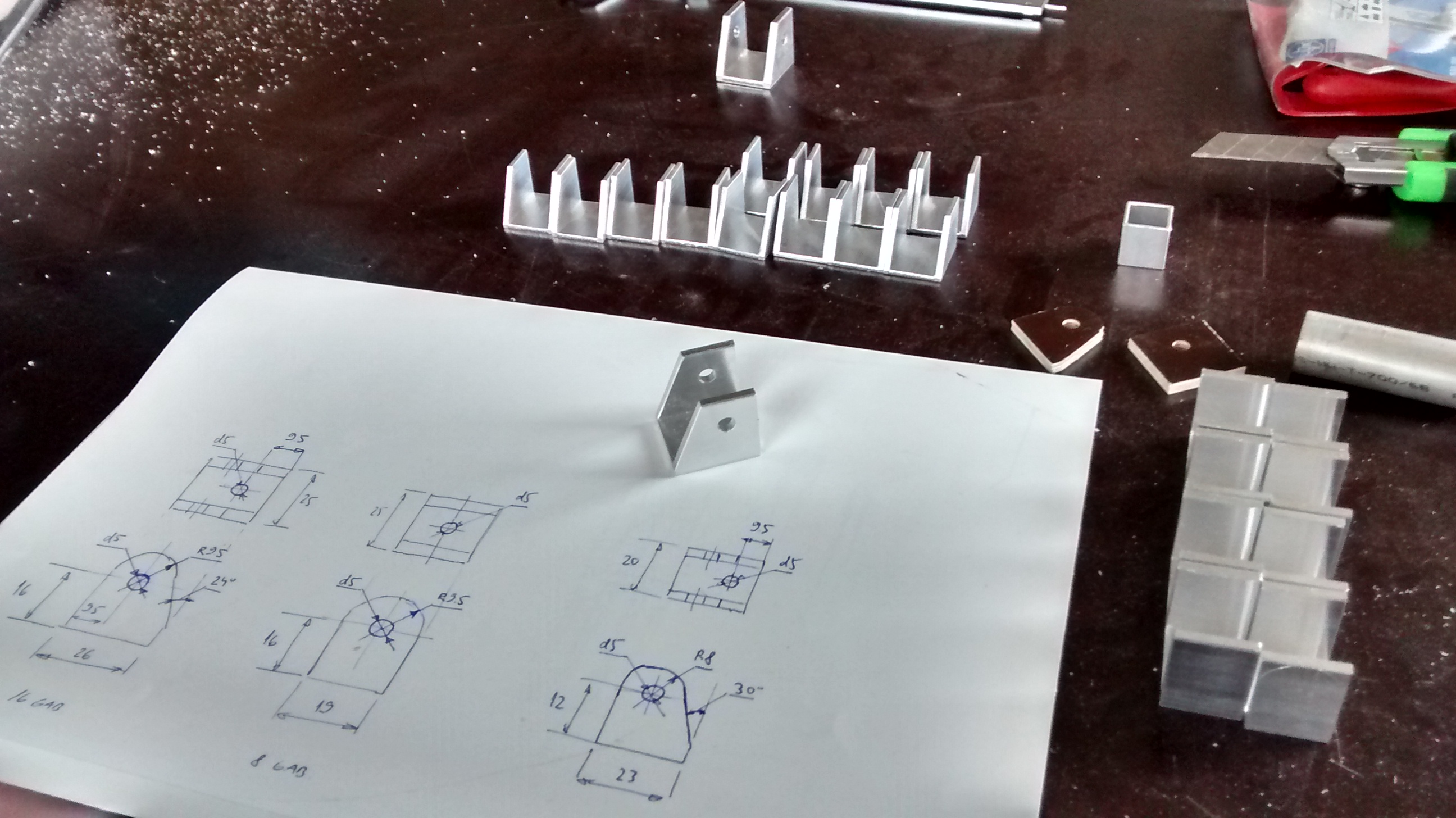
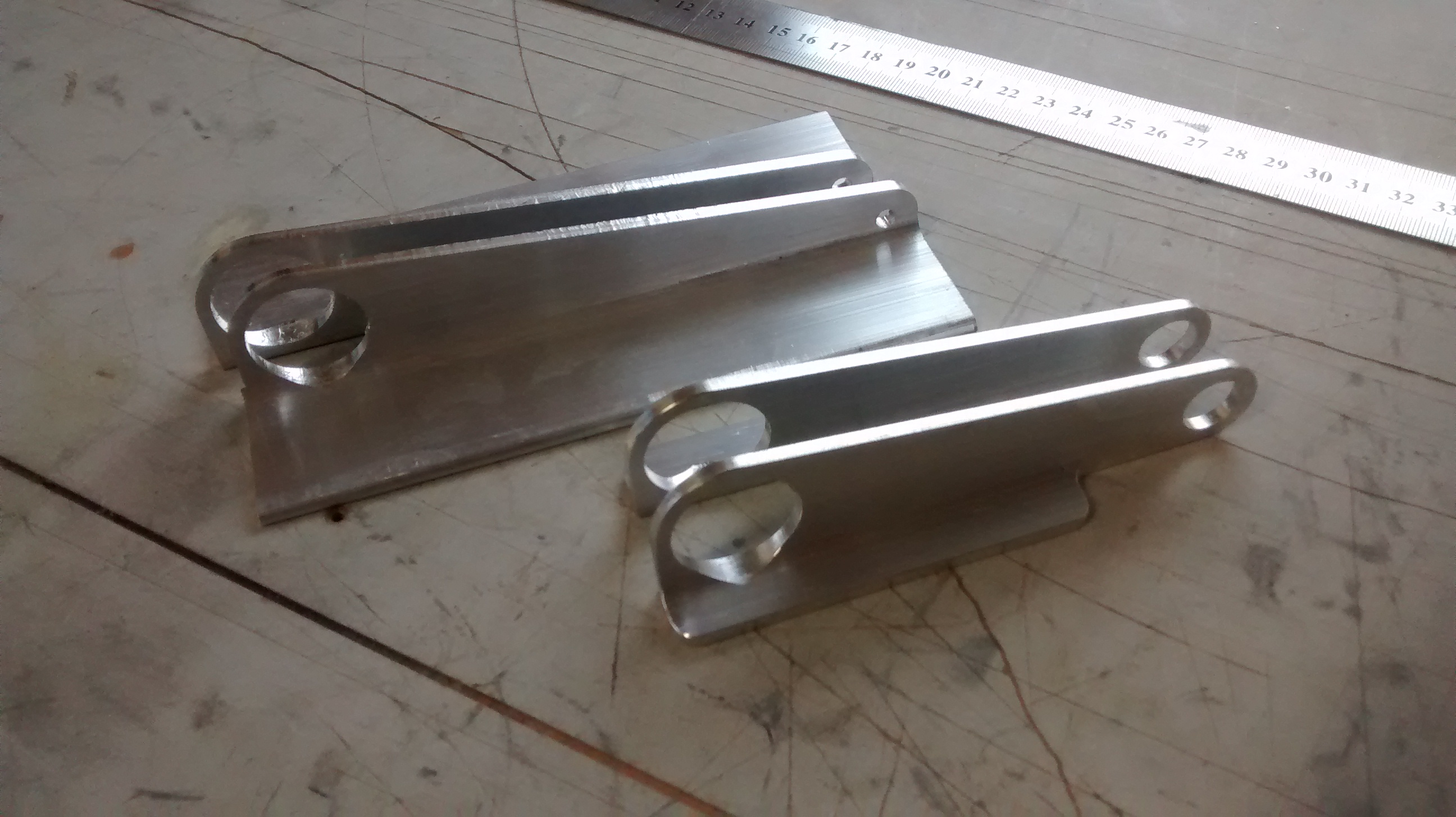
Using the privileges of digital parts, first thing to do was water cutting of parts from 6061T6 SHEET .125 2 X 2. This saved us a lot of time, since all the DXF files for every part were ready.
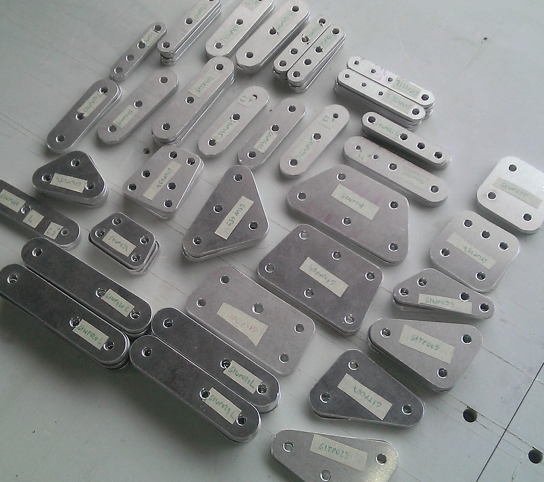
These types of parts are mainly used for tube connections.
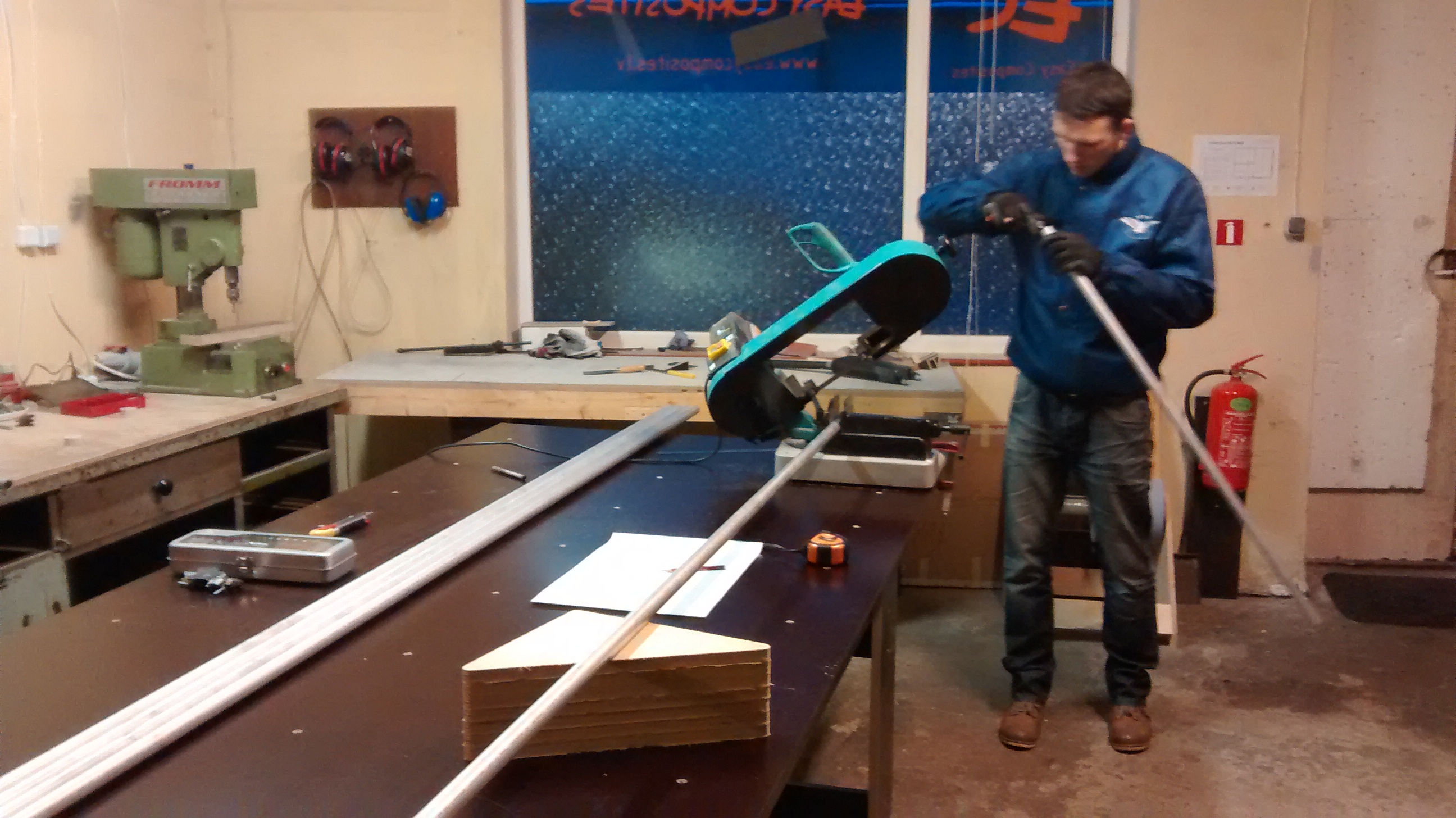
Tubing creates the main structure of Goat glider. Al 6061T6 tubes with 18 different cross-sections are used. First of all tubes are cut into correct lengths using a bandsaw.
Afterwards every piece is tagged with the corresponding part number. All the holes are marked and drilled. From CAD files every tube-based part gets a “drill code”, which tells what size of hole must be drilled at what dimension and angle.
Looks like this: “419 8-d5t0 22.5-d5t90 37-d5t0 47.5-d5t90 385-d4p0 398-d4p0 411-d5t0 e8”
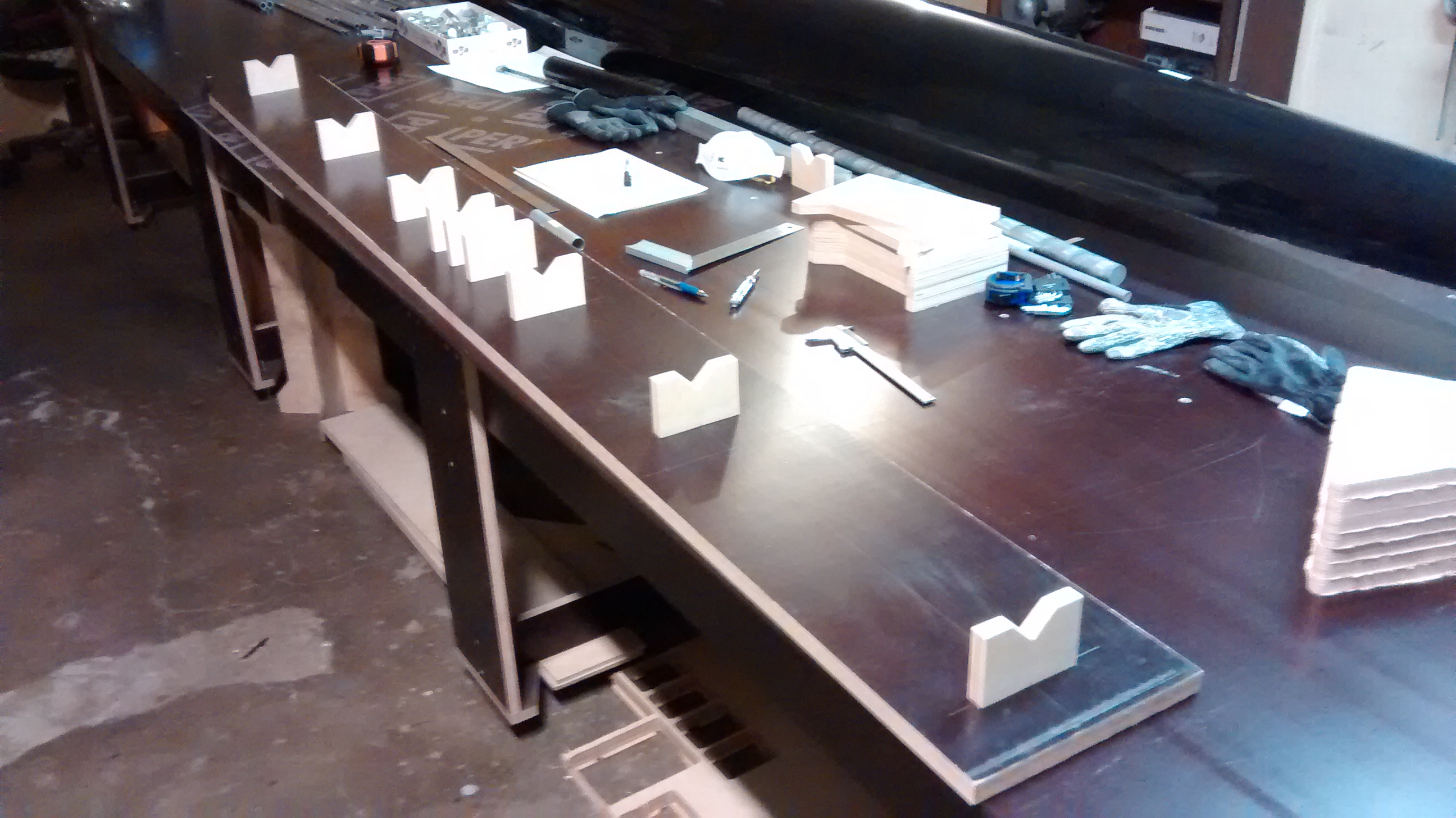
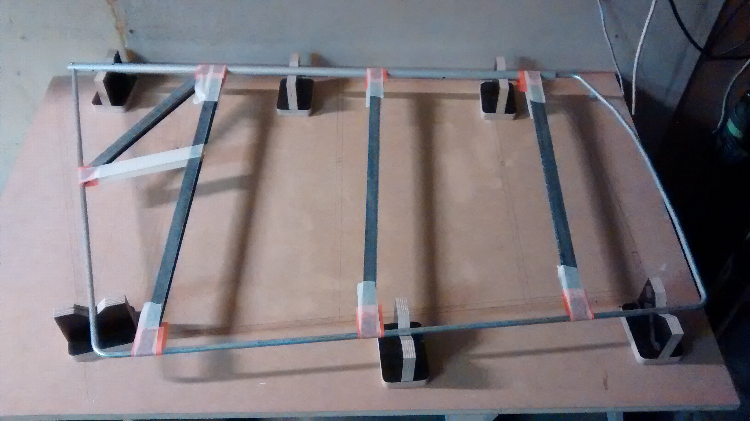
To accomplish the task a special jig was built for correct tube alignment and rotation possibility.
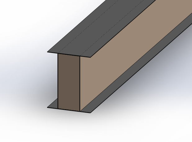
Some of the tubes need local increase of wall thickness, which is achieved by inserting another shorter tube, the so called “sleeve” into the main tube. To get the correct fit between the OD of inner tube and ID of outer tube the sleeves are wrapped with glass fiber cloth wetted with epoxy resin.
There are also parts made of U-channel aluminum profiles and angle profiles. Most of these parts we are making by hand, however for some parts we utilize CNC milling. Al 6061T6 angle profiles we got from Aircraft Spruce, however U-channels are offered from 6063 T52 aluminum alloy only, which is much weaker. Therefore for highly loaded assemblies, like wing strut connections we had to custom-mill the U-channels from 6082 square bars. For assemblies carrying lower loads we used commercially available U-channels from non-structural aluminum alloy.
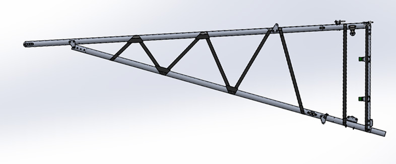
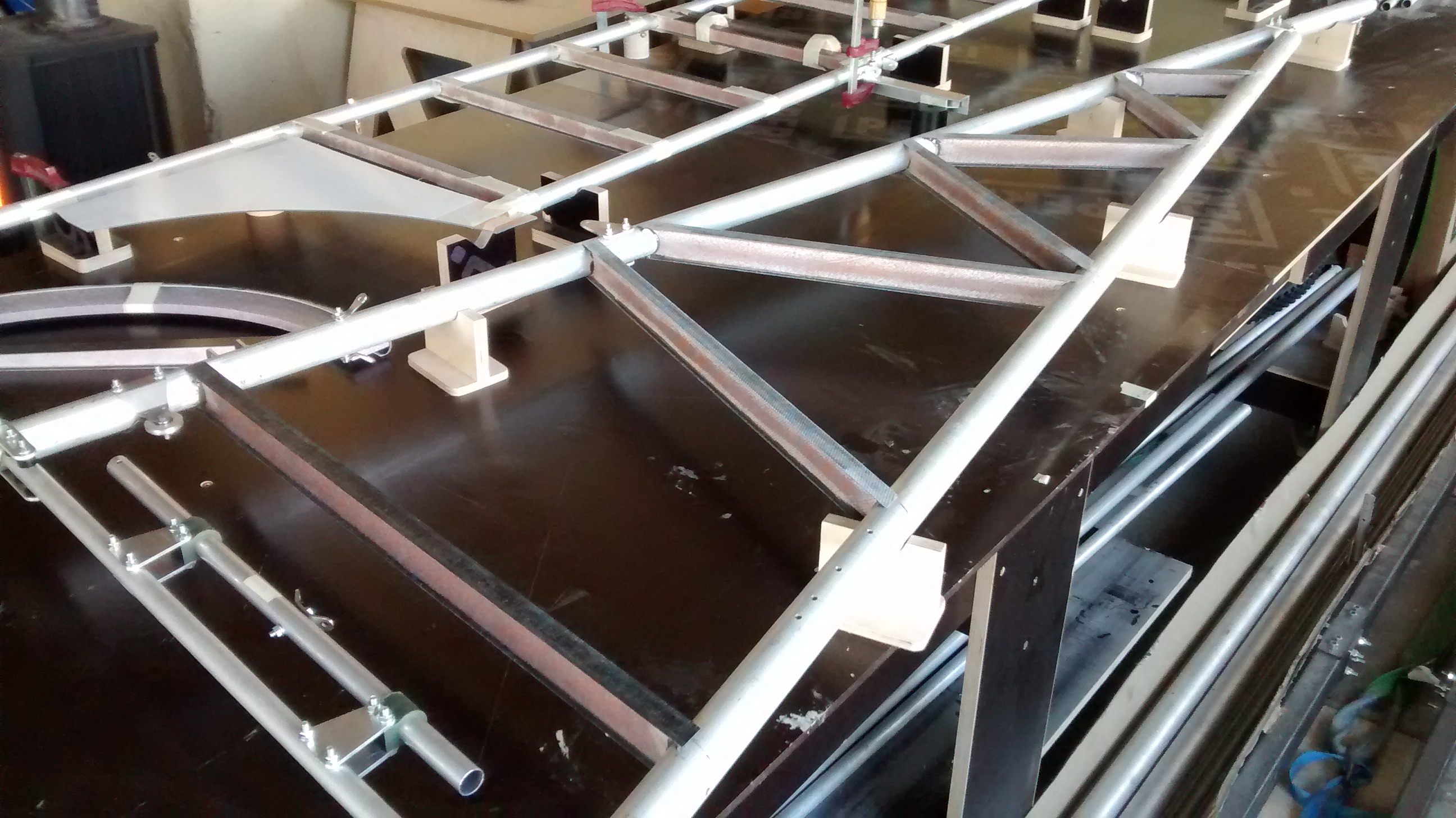
So the part kit for structural assembly of the nose section was ready and we could make the first test of the part manufacturing precision. Everything fit perfectly together.
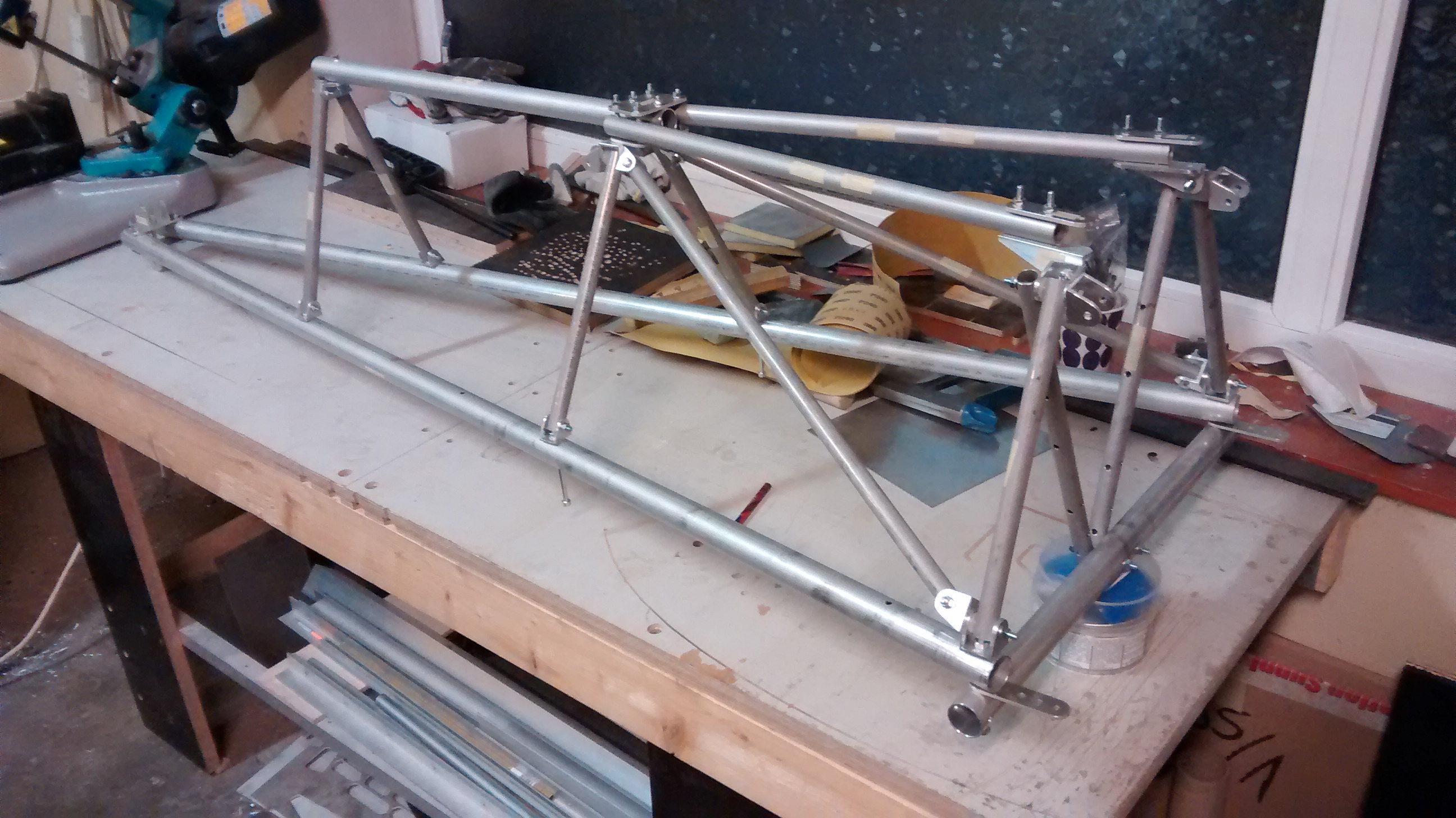
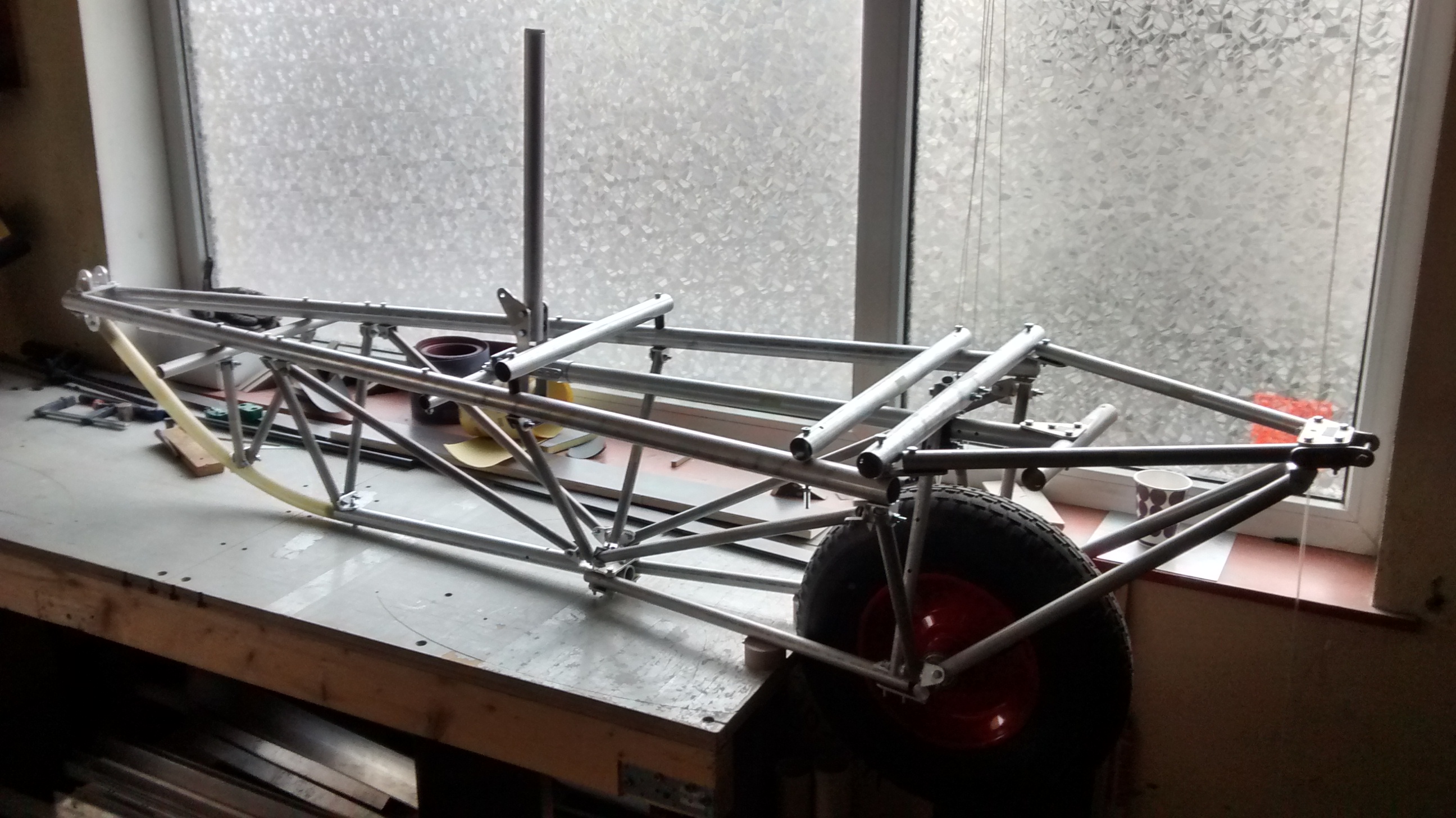
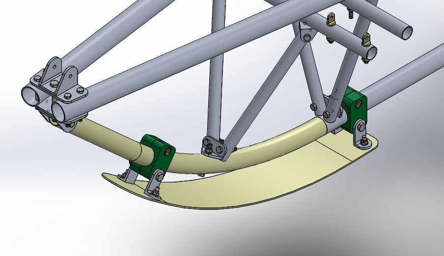
Note the first main difference from the original Goat design – the front lower tube is made of glass fiber for better load absorption from the nose skid.
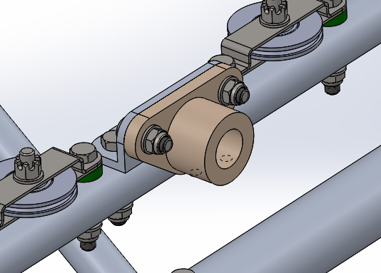
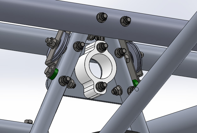
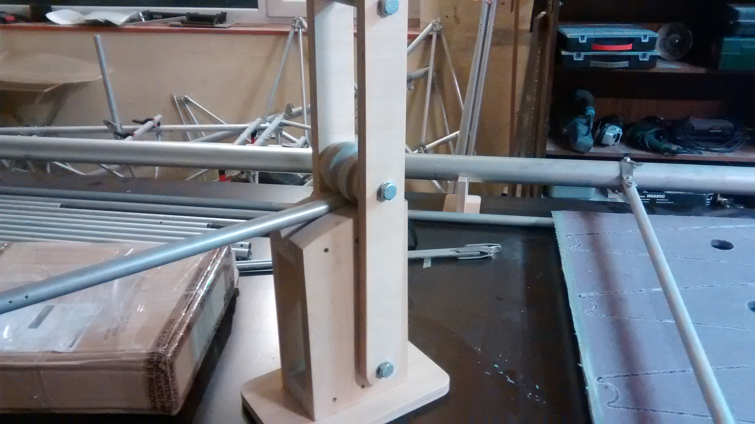
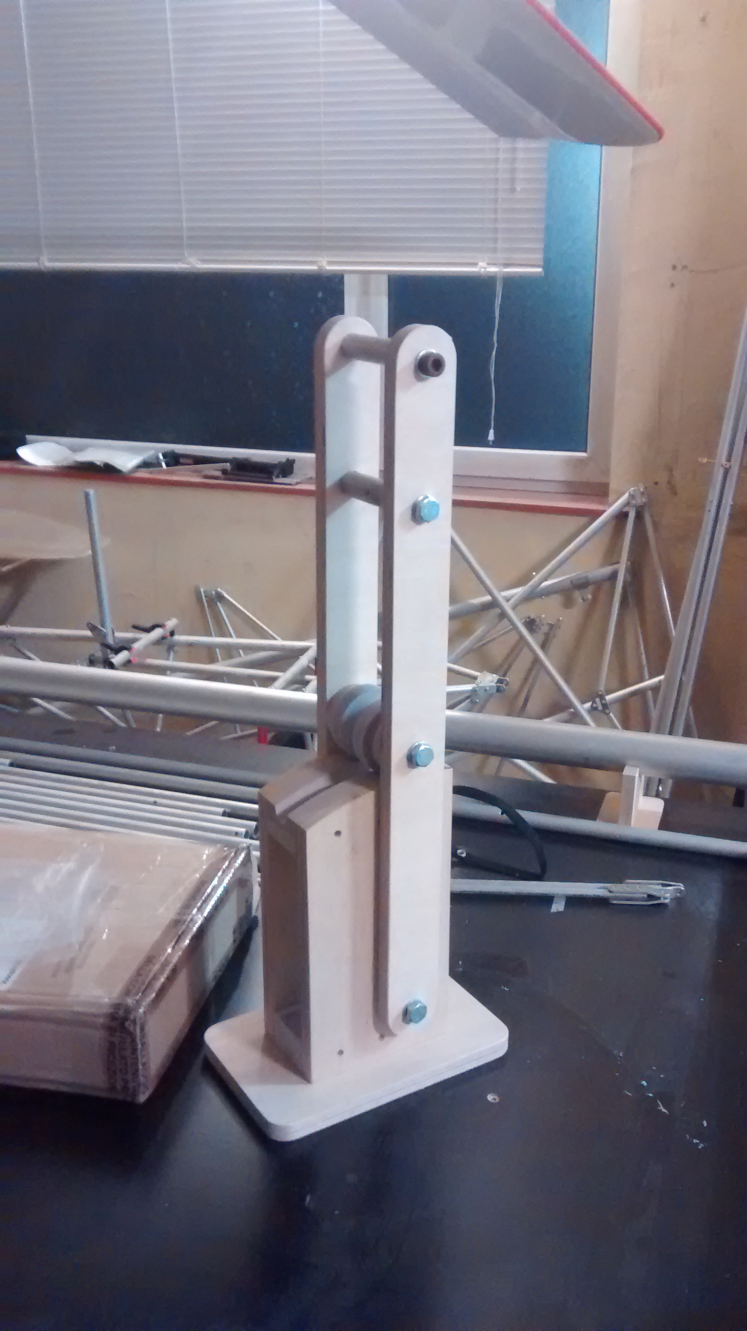
The front and rear holders for flight control torque tube are made of Ertalon LFX nylon using CNC milling process. They will also serve as maintenance-free bearings.
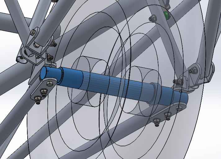
The wheel axle was made of 2024 aluminum rod, which is one of the strongest aluminums for cyclic loading.
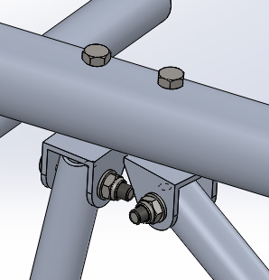
For cabin truss tube connections we widely used parts made of standard U-channels 20x20x2mm.
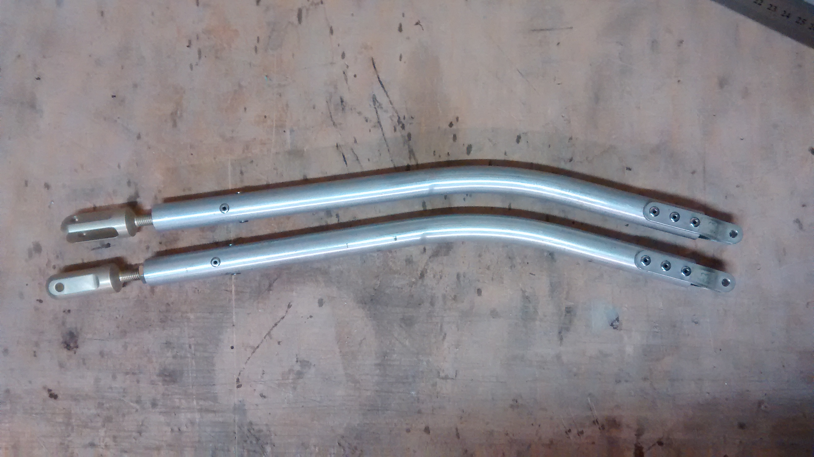
A challenge for us was the tube bending. Fortunately there are not much bent tube parts in Goat assembly, but there are some that required bending. These are push/pull elements for aileron control as well as trailing edge tubes for rudder and elevator. So we made a custom tool for ¾ inch tube bending.
In the result there were nicely bent tube parts:
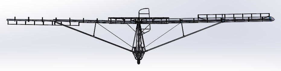
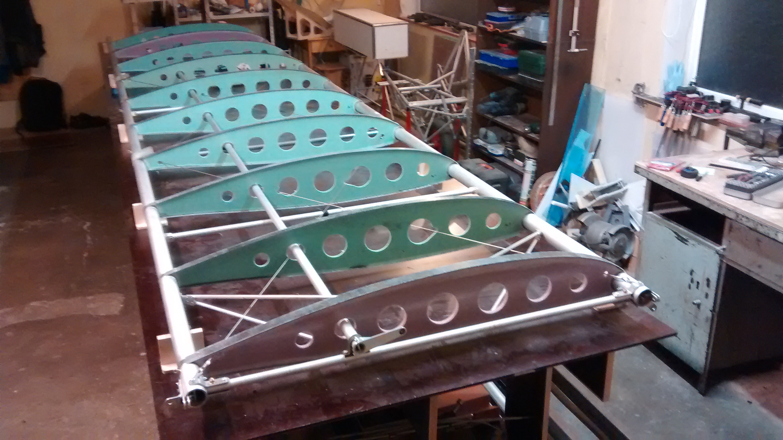
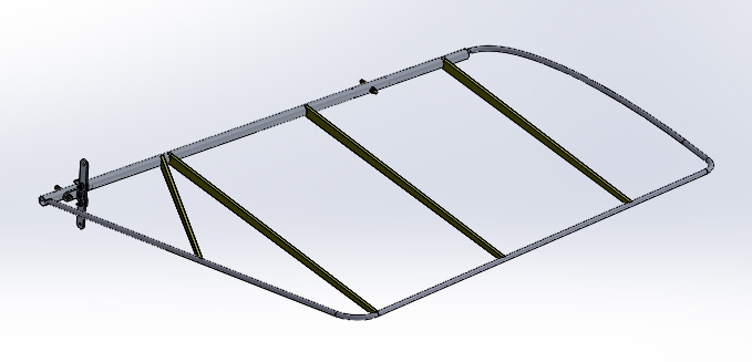
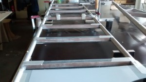
Having all the necessary aluminum sheet parts which were cut early in the beginning and all the tubes cut and drilled we started working on the wing assembly. Along with that wing ribs are being prepared. For the wing we picked an airfoil other than the original one. A low speed airfoil with curved bottom spline would give better low speed stall characteristics as well as less drag.
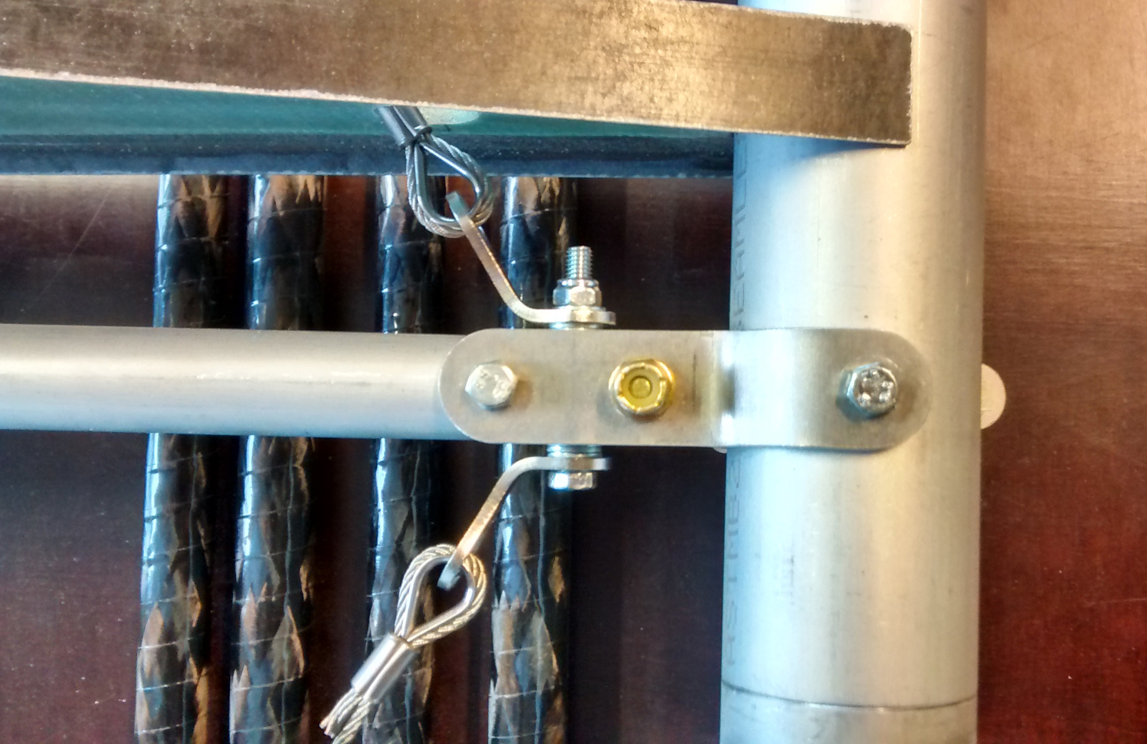
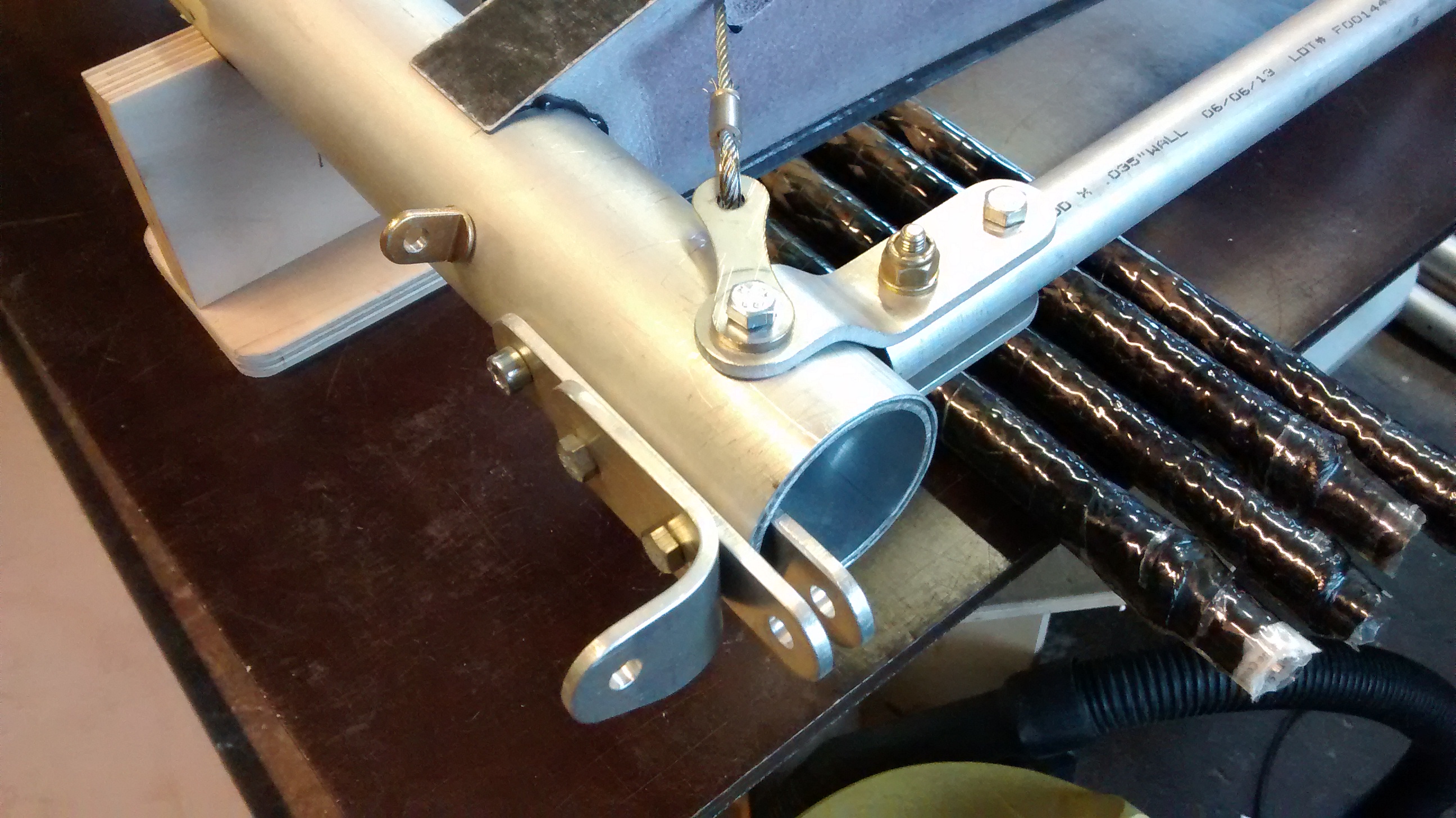
Having all the ribs ready just before putting them in place we made the wing diagonal cable assemblies according to the lengths taken from CAD drawings. These cable assemblies are not adjustable therefore shouldn’t be made too long. If slightly too short they can however be tensioned by putting the necessary amount of shims below the cable thimbles.
Next thing to put into the wing assembly was aileron torque tube. The cranks on both sides of the torque tube were made of 6061 T6 angle using CNC milling and hand tools.
This was also the right time for making the set of torque tube holders.
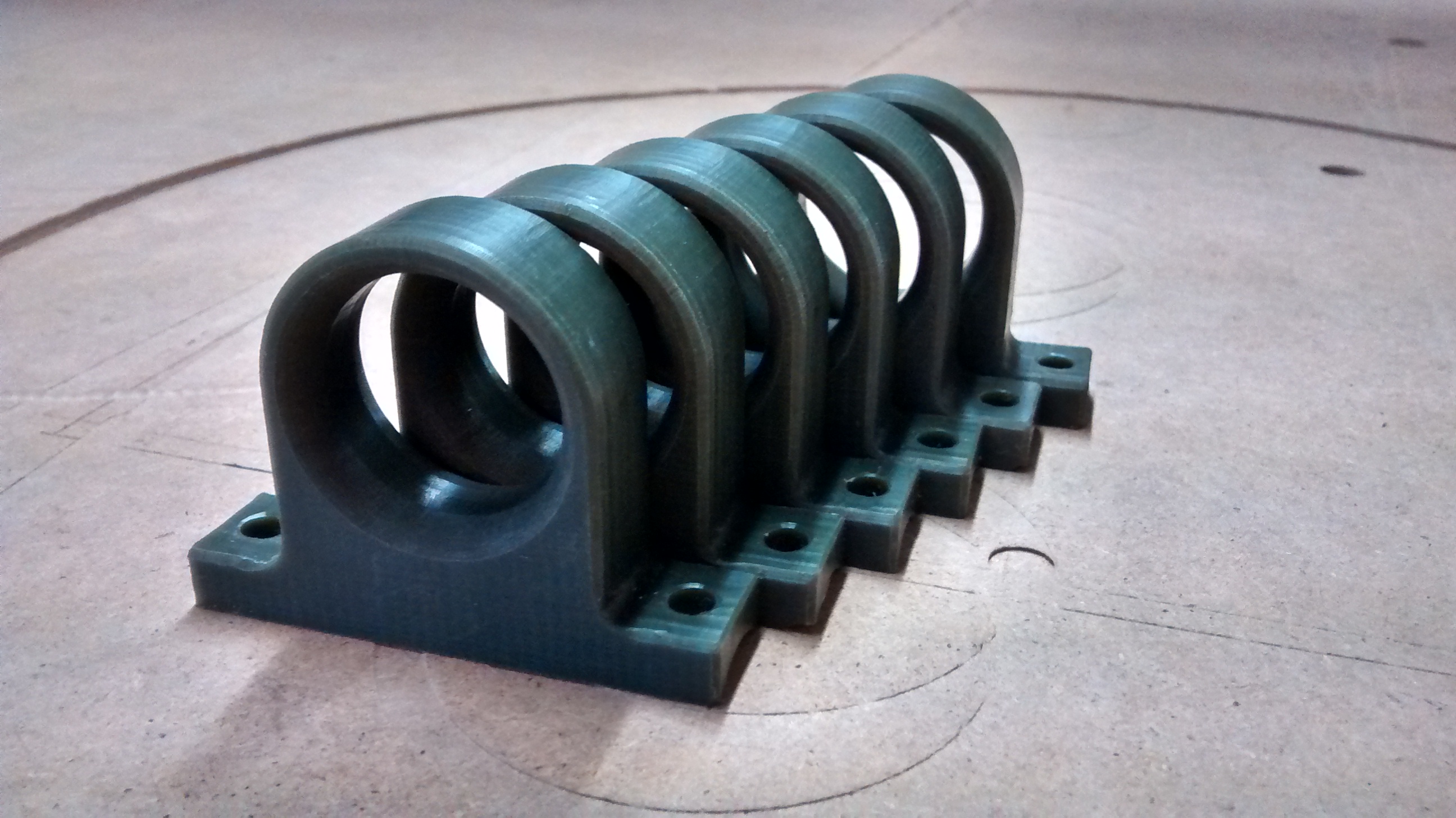
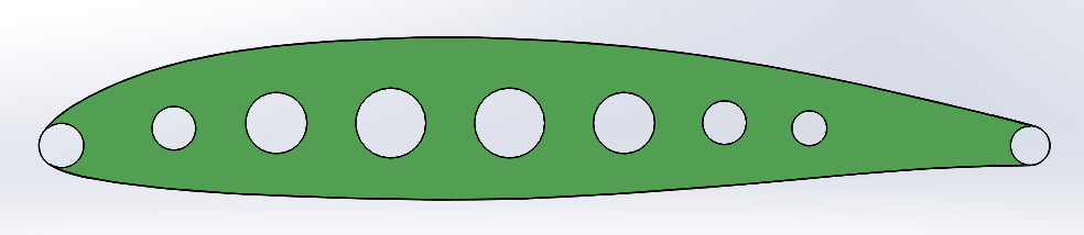
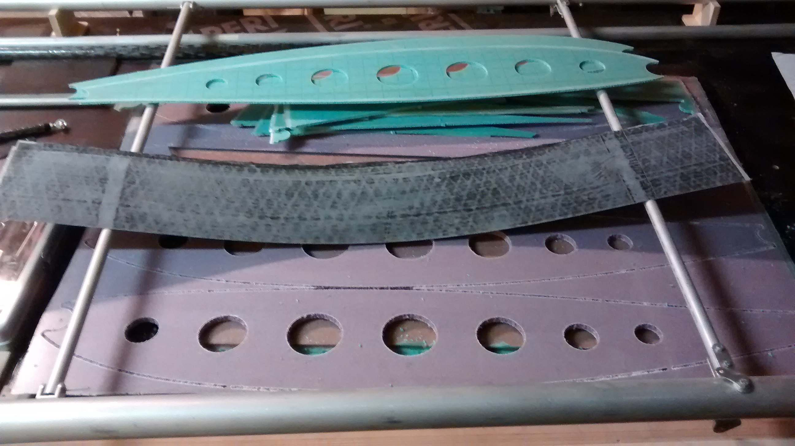
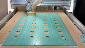
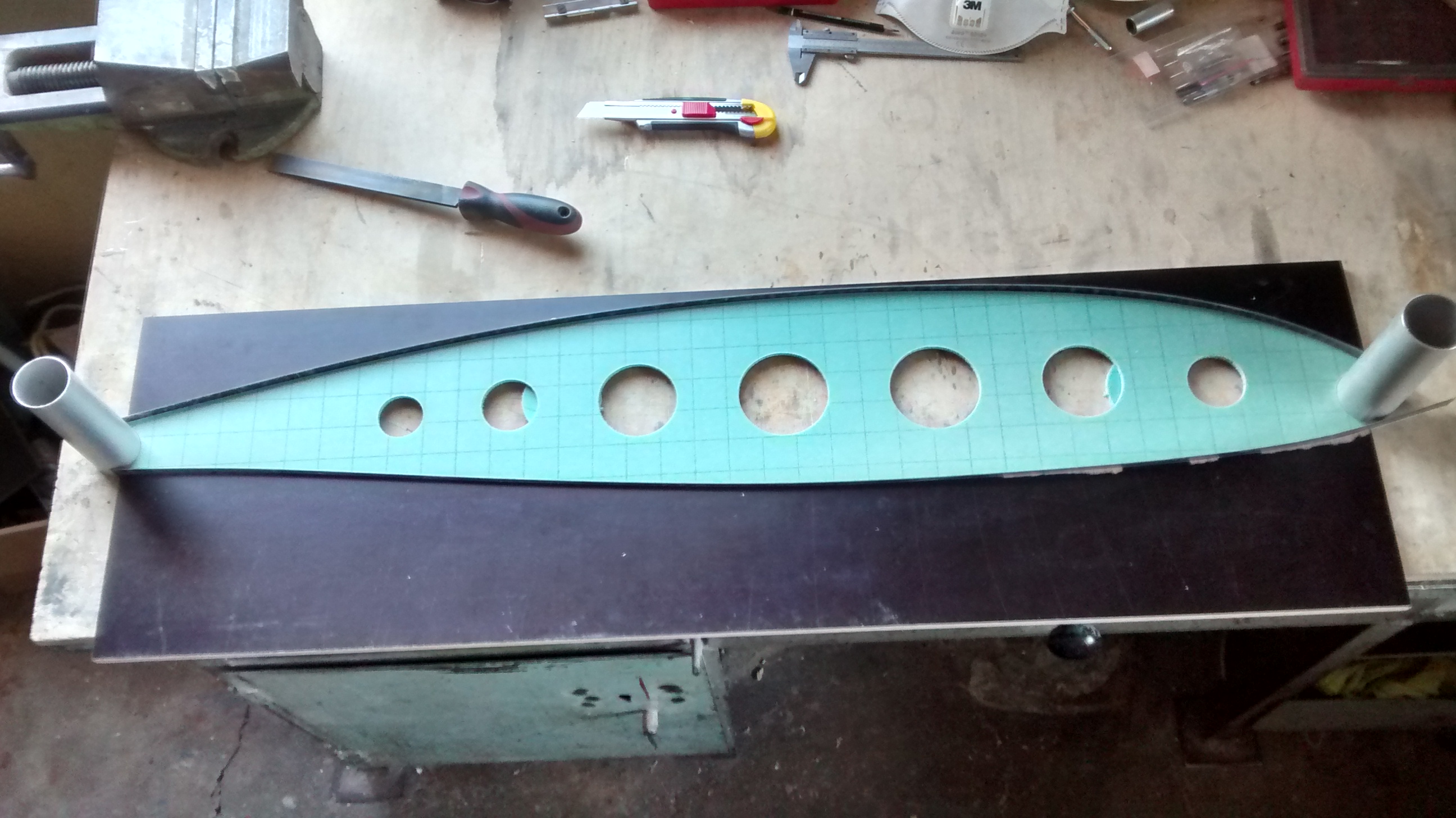
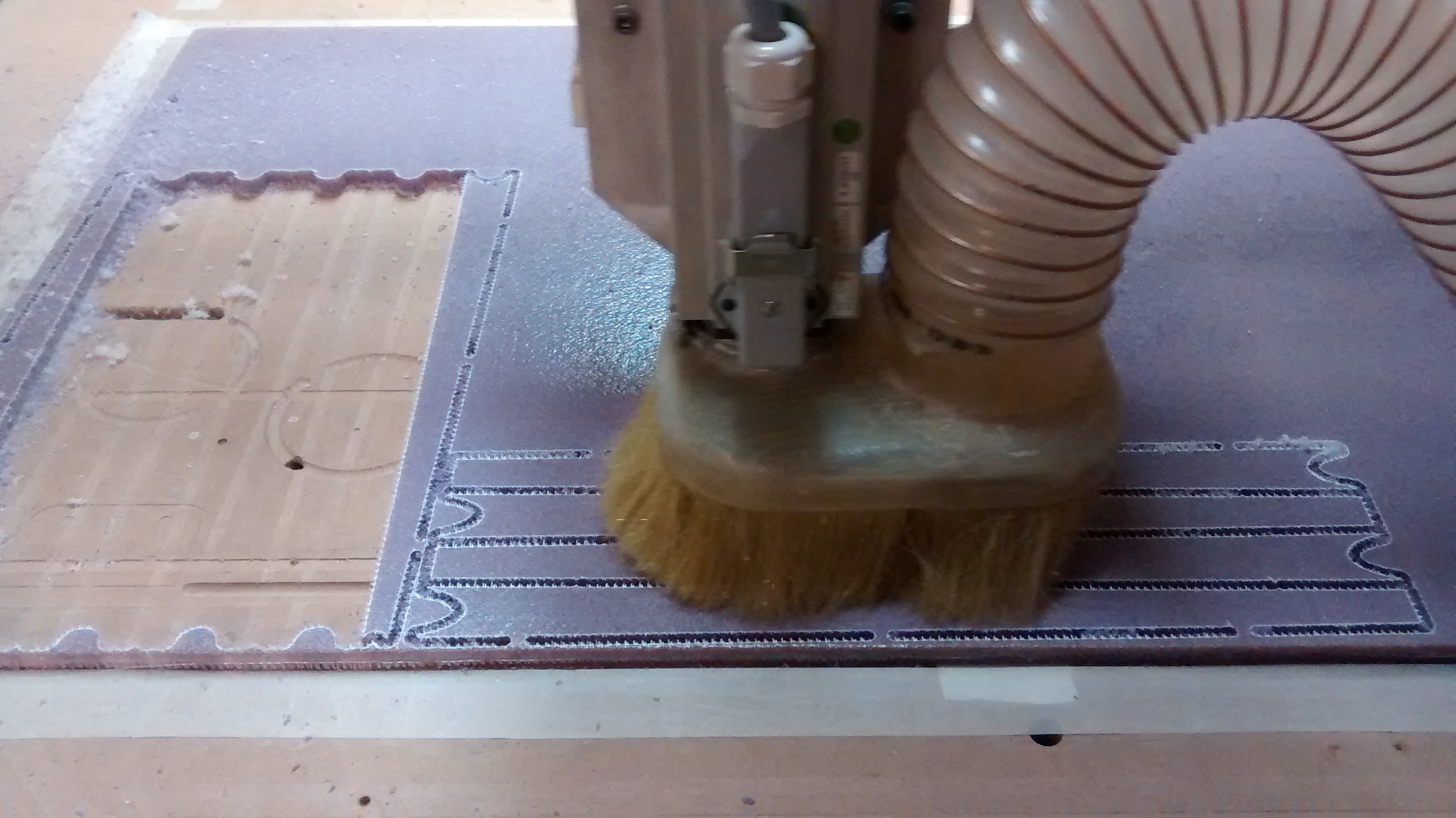
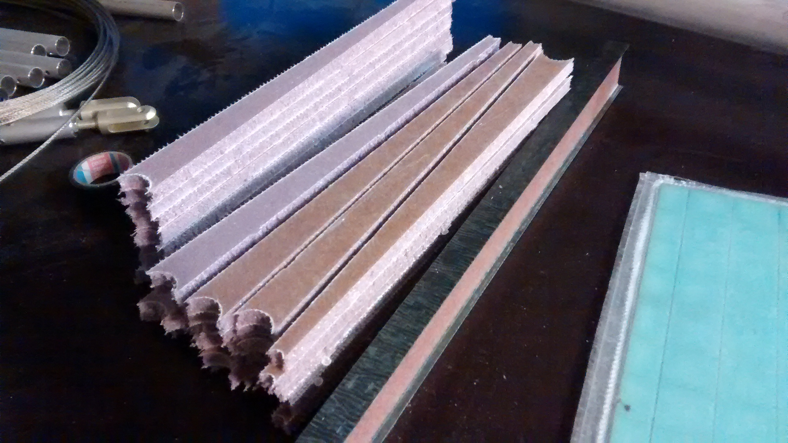
Ribs for the fin, rudder, elevator, ailerons and flaps are of similar construction. We are using CNC milling to cut them from vacuum-prepared sandwich panels.
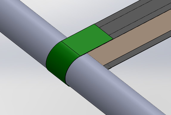
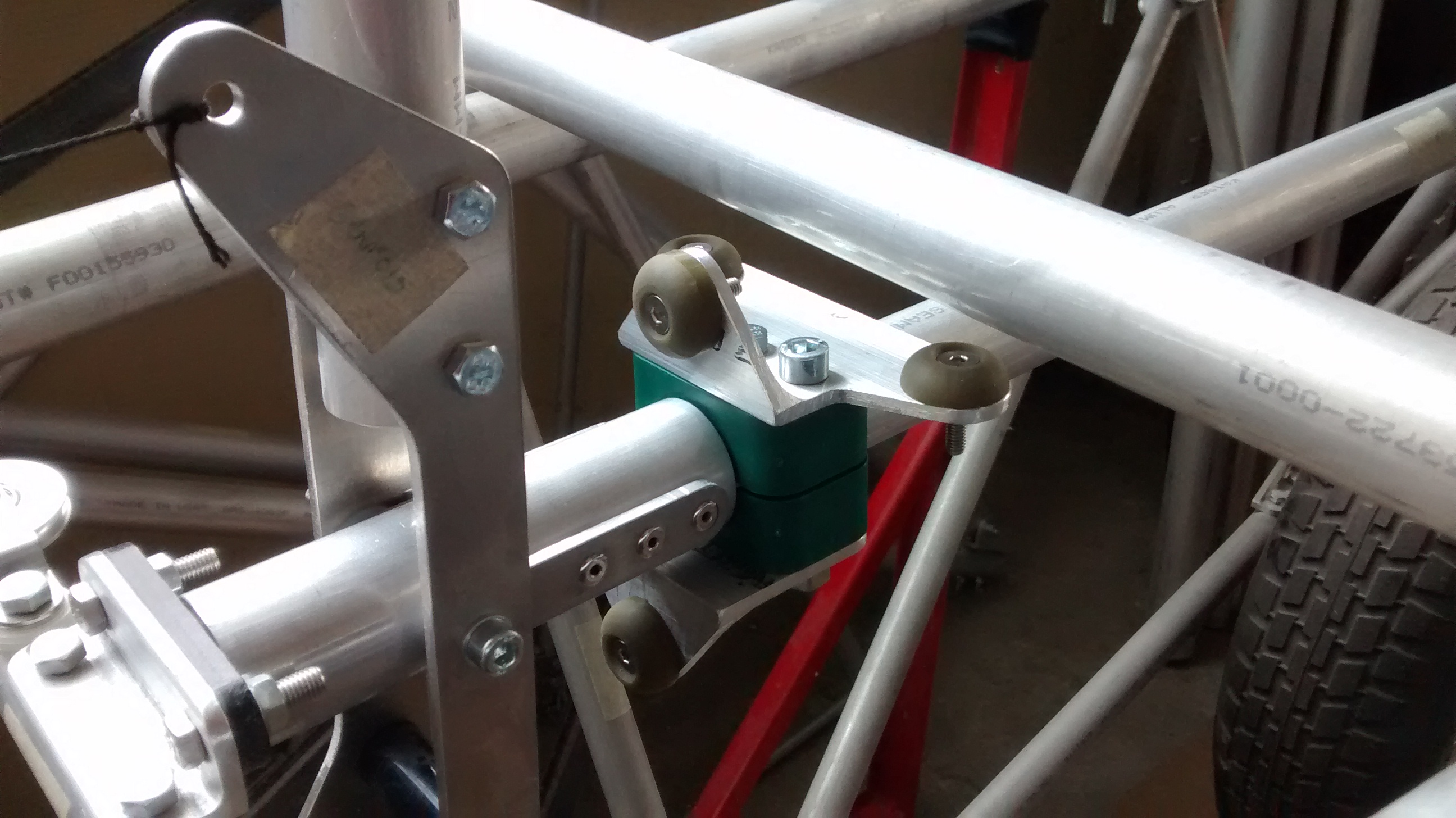
Also the flight control surfaces or Goat are structurally similar: leading and trailing edges are formed by Al 6061T6 tubes, which are held together by ribs and additionally fixed by C-clamps (shown in green):
While making the ribs we are starting to assemble the flight controls. First major assemblies are rudder and vertical stabilizer.
Rudder assembly is quite simple – it consists of straight leading edge tube, bent trailing edge tube, 4 ribs, cable control lever and its brackets. Similarly the vertical stabilizer accommodates 8 ribs distributed between the upper and middle tail boom tubes:
Horizontal stabilizer is composed of two parallel 1 inch OD tubes connected by 8 parallel ribs and 2 circular stabilizer tip ribs. With these tip ribs we replace the original bent tip tubes to keep the same profile thickness along the entire span and increase stiffness.

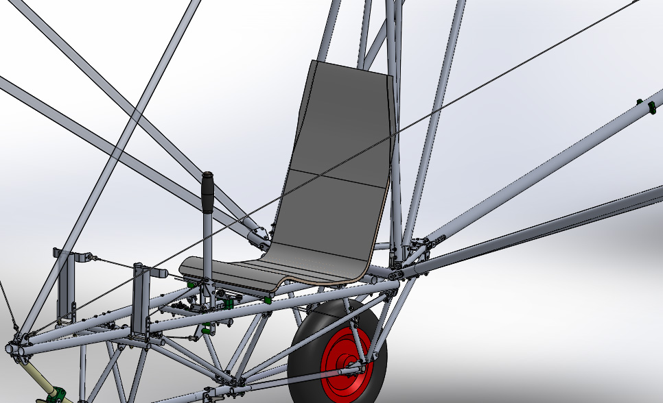
After multiple revisions of seat design we came up to a rather simple solution. The seat itself would be a glass fiber sandwich shell made on a 2-D extruded mold. Such a simple technology would produce a strong and lightweight seat.
A piece of styrofoam was put between two CNC-milled end-profiles. The excessive foam was removed along the profiles with a hot wire. The styrofoam surface was then finished with a two layers of glass fiber. This surface will be re-finished and ready to make the seat shell.
In the meantime we are continuing with assembly of flight control surfaces.
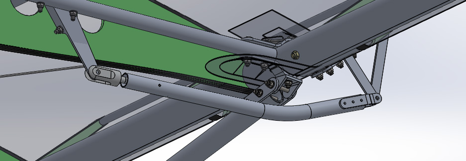
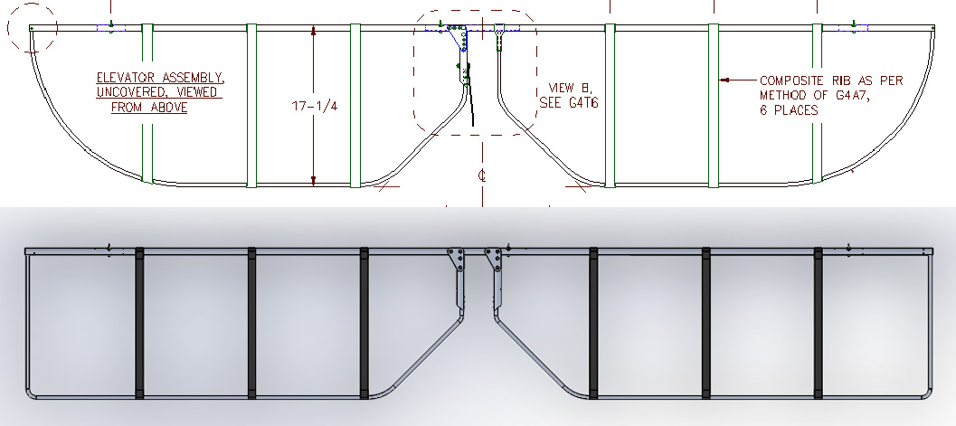
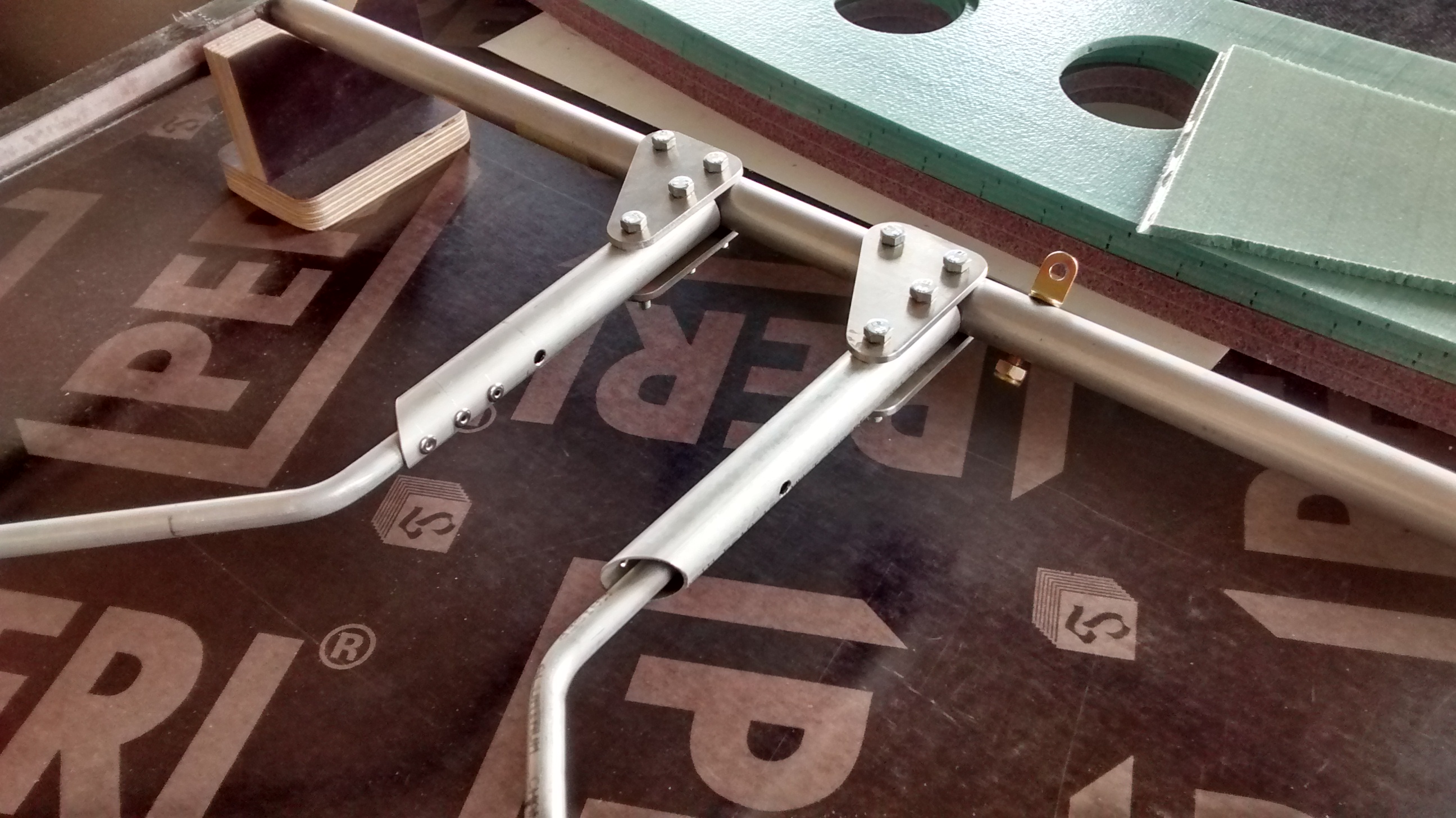
Elevator structural assembly is similar to rudder – it consists of straight leading edge tube, two symmetrical bent trailing edge tubes, six ribs, two crank tubes and brackets for control arm attachment.
While examining the leading edge tube torque stiffness, it was decided to slightly alter the original Goat construction be introducing a second control arm symmetrically attached to elevator right hand side crank tube. This would significantly reduce elevator torsional bending during deflection.

While the control surface assembly is in progress we figured out and created some other stuff – the control stops.
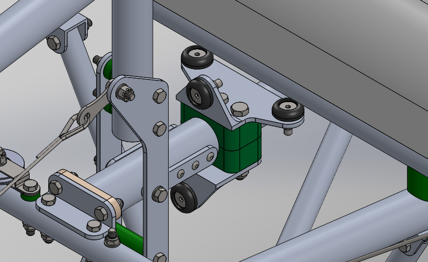
EC Goat design includes adjustable limiting stops for control stick travel. Stop brackets are located on the control stick torque tube. They are attached to the tube using polyamide tube clamps.
Brackets are made of 6061T6 0.125in aluminum angle. The contact elements are made of polyurethane rods shore 90. Control travel angle is adjusted by inserting shims between the contact elements and brackets.
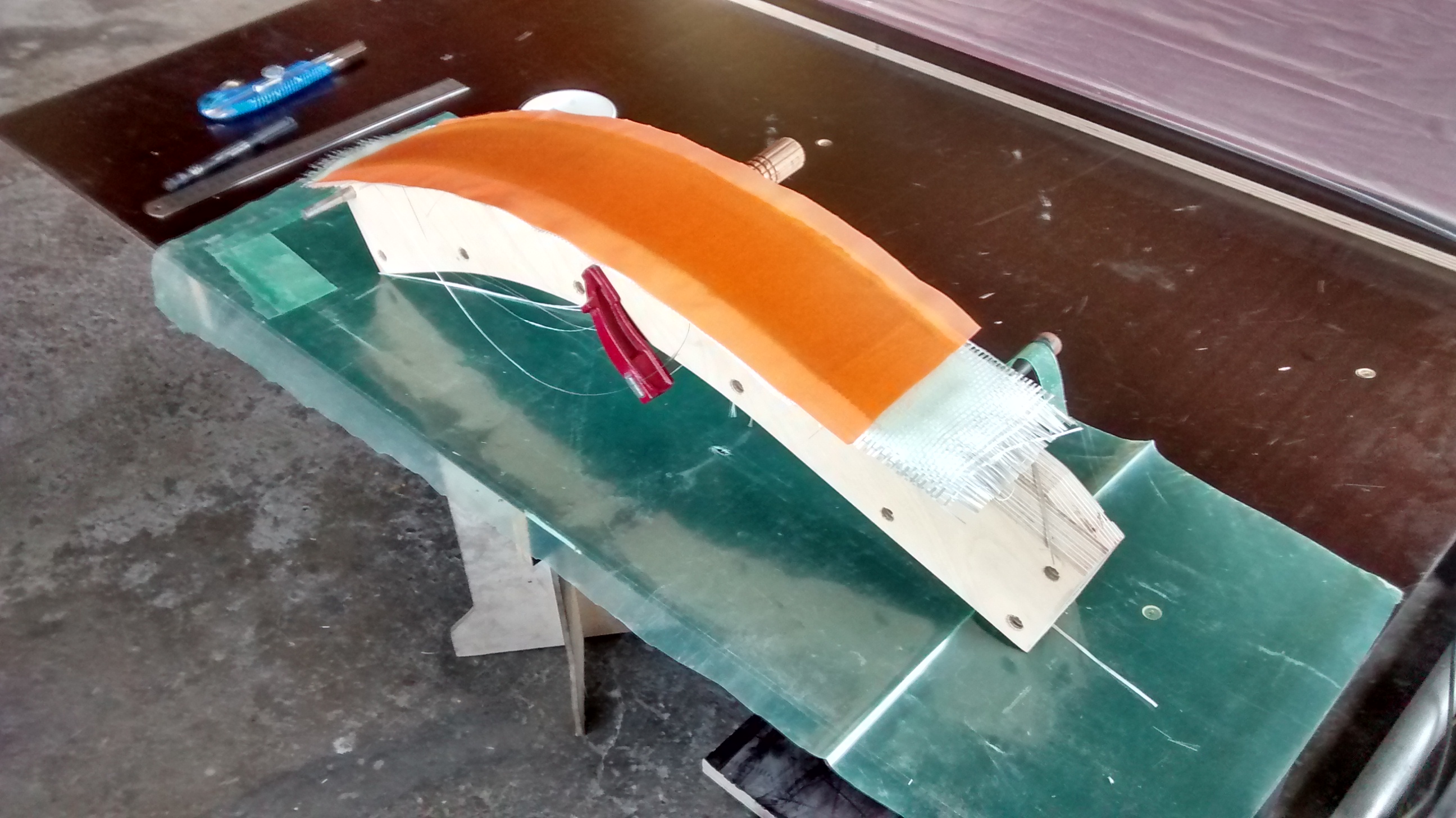
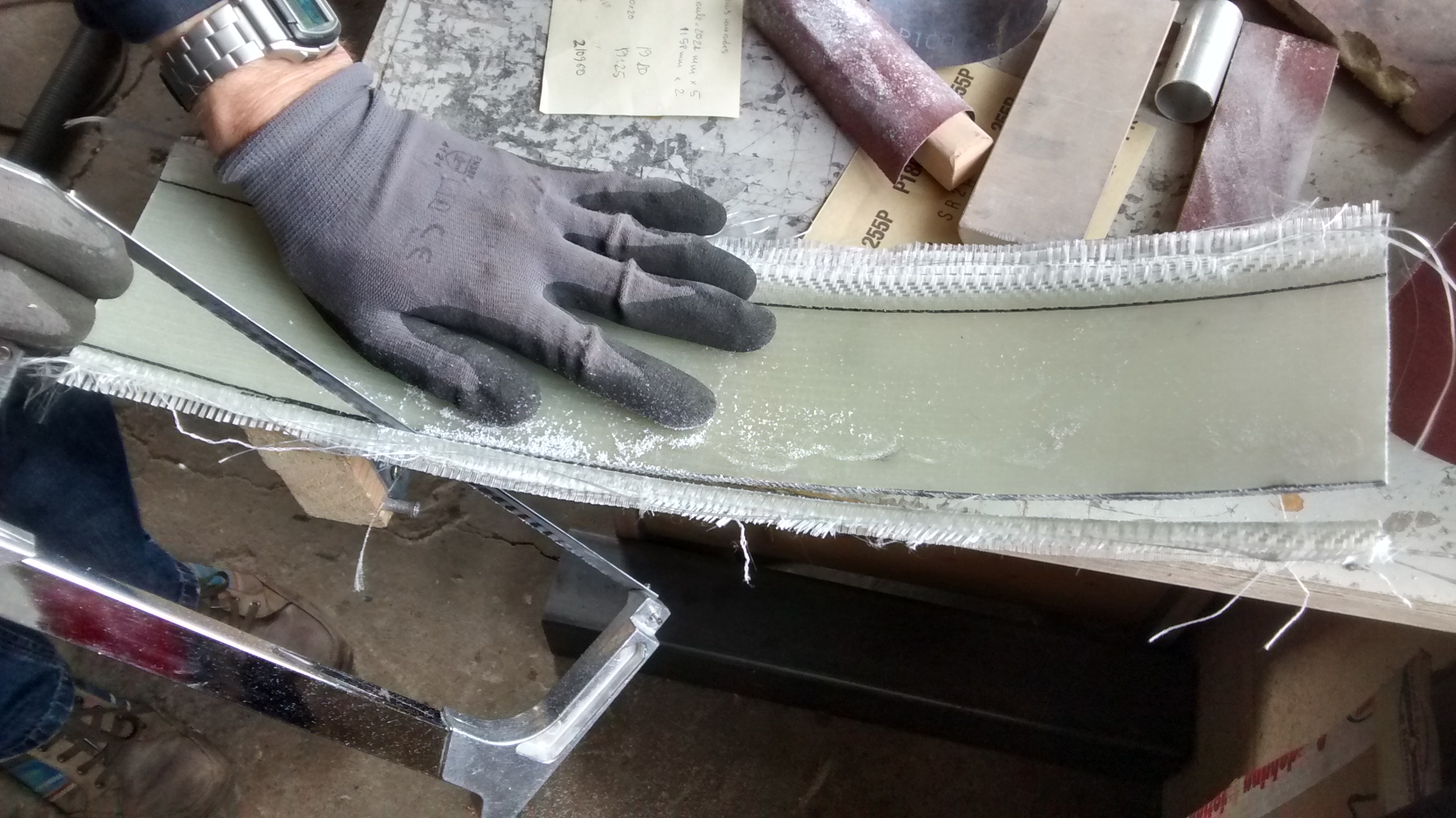
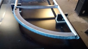
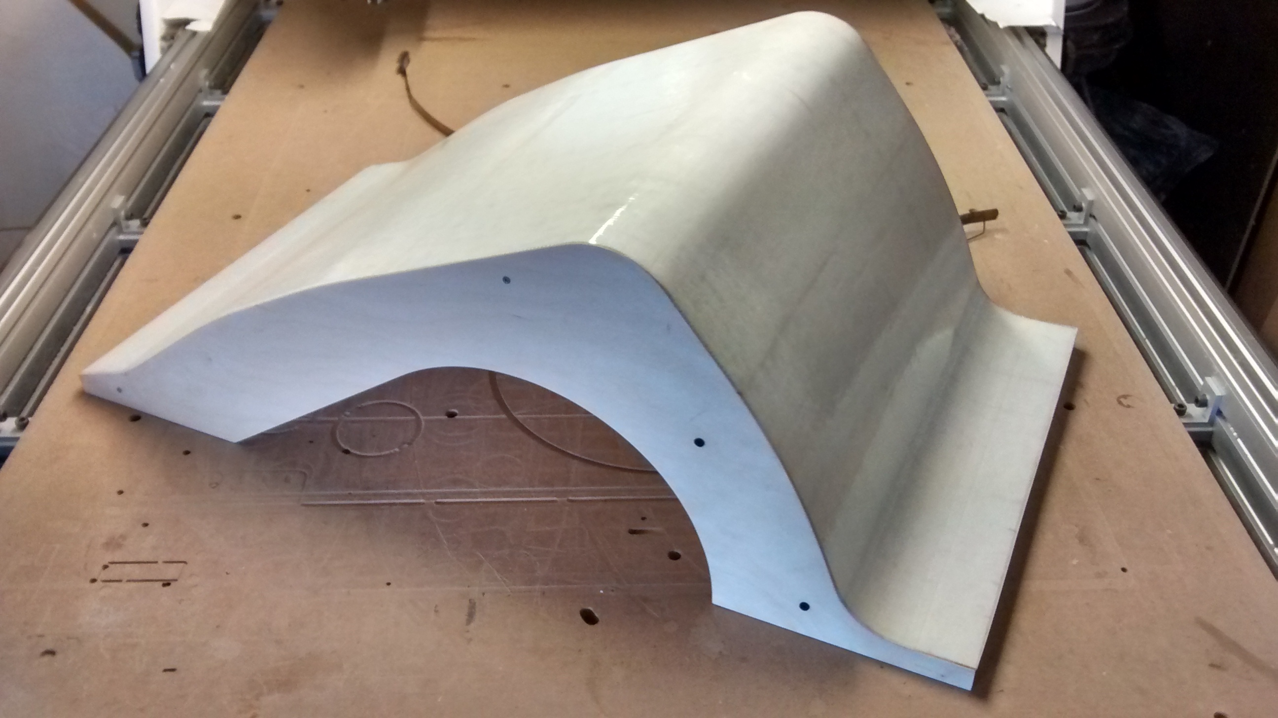
Landing gear on EC Goat is simple: it consists of the main wheel and nose skid. The skid is located on the front lower part of the nose section and serves for two purposes: shock absorption and nose structure protection during ground movements, takeoff and landing. It is made as a curved glass fiber sheet with 2 mm thickness. Skid is attached to the nose skid tube using two pairs of plastic tube clamps, 6061T6 angles and bolts.